
AC Circuit
AC Circuit: Overview
This topic covers concepts, such as, Current versus Frequency Graph for L-C-R Series Circuit, Series LCR Circuit, Phasor Diagram for Pure Inductance Circuit & Phase Difference in Voltage and Current in Pure Inductance etc.
Important Questions on AC Circuit
An a.c. source, of voltage , is applied across a series LCR circuit. Which of the following is the phasor diagram for the circuit when capacitative impedance exceeds the inductive impedance?
In a series circuit, the voltages across an inductor, a capacitor, and a resistor are , and respectively. The phase difference between the applied voltage and the current in the circuit is
Graph showing variation of current with frequency of source in a series circuit is,
A capacitor of capacitance is connected to an alternating source of emf given by . The maximum value of current in the circuit is approximately equal to:
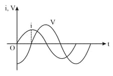
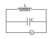
In the givengraph of an circuit, the circuit may be
The phase difference between input between input and output voltage dor the following circuit in (i) and (ii) will be
(i)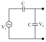 (ii)
(ii)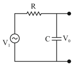
Given below are two statements:
Statement-I: In an ac circuit, the current through a capacitor leads the voltage across it.
Statement-II: In a.c. circuits containing pure capacitance only, the phase difference between the current and the voltage is In the light of the above statements, choose the most appropriate answer from the options given below:
A modulating signal is added to the carrier signal
for amplitude modulation. The combined signal is passed through a non-linear square law device. The output is then passed through a band pass filter. The bandwidth of the output signal of band pass filter will be .
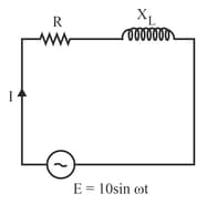
An AC circuit having supply voltage consists of a resistor resistance and an inductor of reactance as shown in the figure. The voltage across the inductor at is:
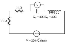
The reading of the A.C. voltmeter in the network shown in figure is (where is in volt)
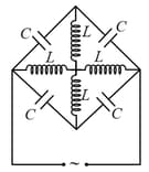
What frequency, sinusoidal AC supply is to be connected to the assembled elements shown in the figure in order that the arrangement have infinite resistance?(neglecting mutual induction between the coils)
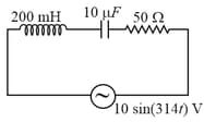
Consider a circuit shown in the figure. Find the energy dissipated in the circuit in minutes.
Statement 1: An ac circuit can be created with zero reactance.
Statement 2: An ac circuit without power is not possible.
In an AC circuit it is found that current leads voltage by . Then circuit may be
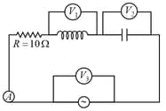
In the circuit shown in figure, the current measured by ammeter is (Readings of voltmeter are as given)
The average power dissipated in a pure inductance is
What is instantaneous power in purely capacitive circuit.
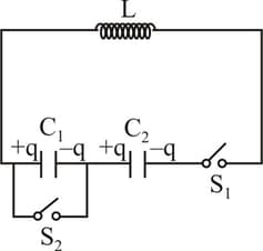
Two capacitors and inductor are connected in series as
shown in the figure. Initially charge on each capacitors are At switch is
closed and at sec, switch is also closed. The maximum charge on capacitor
during LC oscillation is . Find .
An alternating voltage with angular frequency is connected across the capacitor and inductor having and . If the ratio of current through inductor to source is . Find the value of .
When resistance is connected in series with an element , the electric current is found to be lagging behind the voltage by angle . When the same resistance is connected in series with element , current leads by . When are connected in series, the current now leads voltage by which is equal to then the value of is (assume same source is used in all cases)


